


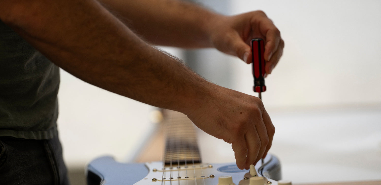


Amazing job! Esasy to install. Top quality
Quality is impeccable, service is just magic. Great product and nice team at O.W
I would have loved a chamfered border on the plate, but it’s already beautiful like that.
I purchased a PC board from this company almost a month ago. It was almost $200. I got a follow up email immediately, but it took almost a week to receive a tracking number. The tracking number has been invalid from the start. Customer service has refused to respond to even one of my several attempts to contact them in order to merely either provide me with the product or make resolution. I feel like I’m almost being trolled at this point because their customer service is literally that nonexistent. I’m gonna have to go through my bank to get my money back. What a huge letdown.
This is a scam clearly. I paid almost $200 for a PC board that never arrived. It’s been almost a month and after three attempts to contact customer service, I haven’t received so much as a courtesy email in response. The tracking information they provided me was invalid and their customer service is nonexistent. It probably won’t even do any good to leave this review because they erased their negative reviews and only allow positive views on the items here on the website. I literally had to challenge this purchase with my financial institution in order to get resolution. If you’re into getting robbed for your hard earned money and ignored when you’re inquiring about your purchase them proceed.
Exactly as promised.
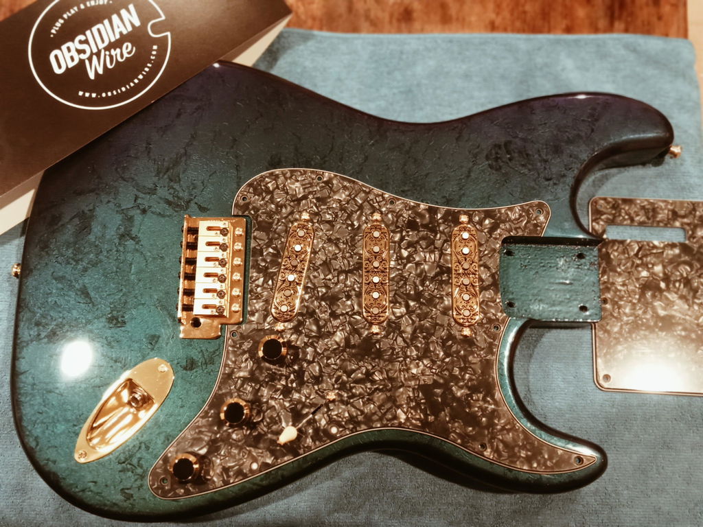
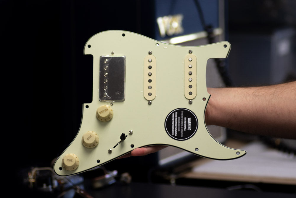
The hardware itself consists of very high quality components with equally high quality assembly.
The packaging was also very good for protecting the loaded pick guard, and considering it was shipped from NZ to Canada (surprisingly quickly) that’s a good thing.
A couple of suggestions to make life even better:
1) More choices of noiseless pickups. I probably would have chosen the APEX HSS set or a milder humbucker (my current favourite is the Thornbucker), but only the APEX+ set was offered.
2) Offer anodized aluminum pick guards. I have an Ultra 2 strat and was hoping to find a loaded pick guard with such an option but couldn’t.
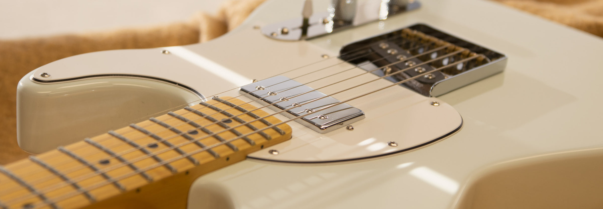
3) Check dimensions of the pickup covers for consistency. The cover of the neck pickup scraped against the slot in the pick guard while the middle was fine.
4) Provide suggestions for better balancing the volume between the single coils and the humbucker. With the APEX + set at the recommended heights, there a pretty big difference
Very good high quality part, it fits, it works i can't ask for more.
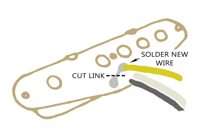
This is my 2nd Obsidian harness. Got the 4-way for my Tele. Easy install but I had a bit of confusion so emailed the company and Mathew responded in 24 hrs with the help I needed. Everything worked great and the Tele sounds fantastic. Highly recommended.
I was very impressed with the quality and functionality of this product, I will be purchasing more for my other guitars.
Simple to install, no problems.
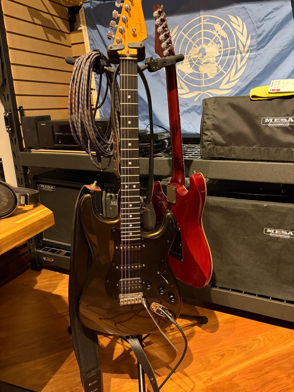
It started with the surprise present from the wife of a custom painted strat body followed by hours YouTube videos. once I had seen the tone rider City limits loaded pick guard from you guys I had to have it. The guitar isn't yet play ready but had to acknowledge the team here on their service and quality build. After making some cosmetic changes Im so excited to hear my pickups thanks for the good work can't wait to play one the build is finished.